A Guide to BGA Rework in PCB Assembly
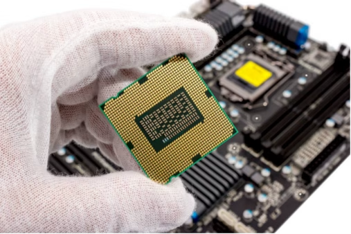
Table of Contents
1. The Precision World of BGA Rework
In the rapidly evolving landscape of modern electronics, Ball Grid Array(BGA) components have become indispensable. From the compact processors in smartphones to the complex ICs powering advanced server and automotive systems, BGAs offer unparalleled advantages in density, performance, and thermal management. However, their unique design, with solder balls hidden beneath the package, presents a formidable challenge when a component fails or requires replacement. This is where BGA rework steps in–a specialized process demanding precision, expertise, and the right equipment to ensure the functionality and reliability of Printed Circuit Board Assembly(PCBA).
BGA rework encompasses the meticulous removal, preparation, and re-attachment of these high-density components. Unlike traditional components with visible pins, BGAs cannot simply be hand-soldered, making rework a critical operation in both manufacturing and repair scenarios. A successful BGA rework minimizes downtime, extends the service life of complex electronic systems, and prevents the costly scrapping of entire boards. This comprehensive guide will delve into the intricacies of BGA rework, covering the essential processes, tools, and best practices to achieve reliable results, whether you’re a seasoned technician or new to PCBA repair.
2. Understanding Ball Grid Arrays(BGAs) and Why Rework Matters?
2.1 What are BGAs?
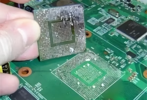
Ball Grid Array(BGA) packages represent one of the most advanced surface mount technologies in modern electronics. Instead of conventional leads or pins extending from the side, BGAs utilize an array of solder balls on the underside of the component to establish both electrical and mechanical connections with the PCB. This innovative design allows for significantly higher pin counts, superior thermal performance due to a larger contact area for heat dissipation, and a much smaller overall package size compared to traditional leaded components. BGAs are pervasive in crucial components like microprocessors, memory chips, and Field-Programmable Gate Arrays(FPGAs) in almost every sophisticated device today.
2.2 Why is BGA Rework Essential?
Despite their benefits, the hidden nature of BGA solder joints makes repair incredibly challenging. When a BGA component fails functional testing, exhibits defects after initial assembly, or requires an upgrade, simple replacement is not an option. This necessitates BGA rework. Common scenarios requiring this specialized intervention include:
- Manufacturing Defects:Issues such as solder bridging, voids, cold joints, or insufficient wetting during the initial PCB assembly process.
- Field Failures:Components failing after deployment due to factors like thermal cycling stress, mechanical shock, or material fatigue.
- Engineering Change Orders(ECOs):Situations where a component needs to be upgraded to a newer revision or replaced with a different part for design modifications or performance enhancements.
Without reliable BGA rework techniques, entire, often expensive, circuit boards would have to be discarded. A botched BGA rework carries significant risks, including damage to adjacent components, lifting of PCB pads, cracking of the PCB substrate, or the creation of hidden solder defects that might pass visual inspection but fail catastrophically in the field. For high-reliability applications such as aerospace, medical devices, and military systems(often referred to as IPC Class 3), the consequences of poor rework can be catastrophic, emphasizing the critical importance of mastering this process.
3. The Step-by-Step BGA Rework Process
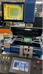
Successfully performing BGA rework requires a precise, multi-stage process, typically carried out on a dedicated BGA rework station. Each step is critical to ensuring the integrity of the component, the PCB, and the final solder joints.
3.1 Component Removal
The first step involves safely removing the defective BGA. This is accomplished using a BGA rework station that applies localized heat to melt the solder balls beneath the component. Crucial aspects include:
- Preheating:The entire PCB is often preheated from the bottom to reduce thermal stress on the board and surrounding components, preventing warping or damage.
- Localized Topside Heating:A controlled hot air or IR heater focuses heat directly onto the BGA package. The heating profile—temperature, ramp rates, and dwell times—is meticulously managed to match the solder paste’s reflow characteristics.
- Component Lift:Once the solder reaches its reflow temperature, a vacuum pick-up tool gently lifts the component from the PCB without disturbing adjacent parts or damaging the pads.
3.2 Site Preparation and Cleaning
After removal, the PCB site must be meticulously prepared for the new component. This involves:
- Residual Solder Removal:Any remaining solder on the BGA pads is carefully removed using specialized soldering irons with desoldering braid or vacuum desoldering tools. The goal is to create perfectly clean and flat pads for the new BGA.
- Pad Inspection:The pads are inspected under high magnification to ensure no damage(e.g., lifted pads, scratches) has occurred and that they are free of contamination.
- Cleaning:The entire area is cleaned with appropriate solvents to remove flux residues and other contaminants, ensuring optimal wetting for the new solder joints.
3.3 Reballing(If Necessary)
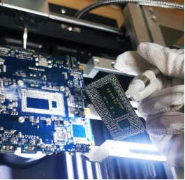
Reballing is the process of replacing the solder balls on a BGA component, typically performed when reusing a removed BGA or preparing a new package that doesn’t come pre-balled. This complex process involves:
- Cleaning the BGA:Residual solder is removed from the BGA’s pads.
- Flux Application:A thin, even layer of no-clean flux is applied to the BGA’s pad array.
- Stencil Alignment:A specialized reballing stencil, precisely matching the BGA’s pad pattern, is aligned and secured over the component.
- Solder Ball Placement:New solder balls of the correct alloy and size are placed into the stencil openings.
- Reflow:The BGA with the stencil is then gently heated to reflow the new solder balls, attaching them securely to the component’s pads.
3.4 Component Placement and Alignment
Accurate placement of the new BGA is paramount for proper electrical connection. This step utilizes the advanced features of a BGA rework station:
- Flux Application:A controlled amount of flux is applied to the PCB pads to promote proper wetting during reflow.
- Optical Alignment:Using an integrated vision system(often a split-field optic camera), the new BGA is precisely aligned with the corresponding pads on the PCB. The camera displays magnified images of both the BGA’s solder balls and the PCB pads, allowing the operator to achieve perfect registration.
- Gentle Placement:A vacuum pick-up tool gently lowers the BGA onto the fluxed pads.
3.5 Reflow Soldering
With the BGA precisely placed, the component is reflowed to create strong, reliable solder connections. This is similar to the removal process but with strict control:
- Controlled Thermal Profile:The rework station applies a precise thermal profile, gradually ramping up heat to preheat the component and board, then increasing to the peak reflow temperature for a controlled duration, and finally allowing for a gradual cool-down. This profile is critical to prevent thermal shock, ensure proper wetting, and minimize defects.
3.6 Post-Rework Inspection
The final and crucial step is thorough inspection to verify the quality of the rework:
- Visual Inspection:Using high-magnification optics, technicians check for proper alignment, solder bridging, and obvious defects around the perimeter of the BGA.
- X-ray Inspection:For hidden solder joints, X-ray inspection is essential. It provides a non-destructive view of the solder balls , allowing detection of voids, bridging, opens, and proper sphere formation.
- Functional Testing:The PCB assembly is subjected to functional tests to ensure the BGA and the entire board operate correctly.
4. Essential Tools and Equipment for BGA Rework
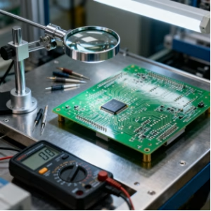
Performing successful BGA rework requires a suite of specialized tools, with the BGA rework station being the central piece of equipment. Here’s a breakdown of the key tools:
- BGA Rework Station:This is the core of the operation, featuring controlled top and bottom heaters(hot air or infrared), a vacuum pick-up system for component handling, and an optical alignment system. Advanced stations offer precise temperature profiling and software control.
- Preheaters:Often integrated into the rework station, but sometimes external, preheaters provide uniform heat to the entire PCB to minimize thermal stress during localized heating.
- Flux Dispensers:Automated or manual systems for applying precise amounts of flux to the PCB pads or component balls.
- Solder Paste Dispensers:For reballing, these ensure consistent application of solder paste if stenciling with paste.
- Reballing Stencils and Fixtures:Stencils with precise openings matching the BGA’s pad array are used for depositing solder paste or placing solder balls during the reballing process. Fixtures hold the BGA securely during reballing.
- Desoldering Tools:Specialized soldering irons with various tips, desoldering braid(wick), and vacuum desoldering stations are used to clean residual solder from the PCB pads.
- Microscopes and Vision Systems:High-magnification stereo microscopes are essential for visual inspection before, during, and after rework. Integrated split-field optical alignment systems on rework stations are crucial for precise BGA placement.
- X-ray Inspection System:A non-destructive inspection tool vital for verifying hidden solder joint quality, detecting voids, bridging, and misalignments that are invisible to optical inspection.
- Thermal Profilers:Devices with thermocouples to accurately measure and record temperature profiles during removal and reflow, ensuring optimal heat application.
- Cleaning Supplies:Isopropyl alcohol(IPA) or other specialized PCB cleaning solvents, lint-free wipes, and brushes for residue removal.
5. Best Practices for Successful BGA Rework

Achieving consistently high-quality BGA rework requires adherence to established best practices. These guidelines help mitigate risks and ensure the longevity and reliability of the repaired PCB assembly.
Thermal Profiling and Control
Precise thermal control is arguably the most critical aspect of BGA rework. Developing an accurate thermal profiling is essential for every BGA package and board combination. The profile must:
- Prevent Thermal Shock:Gradual preheating and cooling minimize stress on components and the PCB substrate.
- Ensure Proper Reflow:Reach the solder’s melting point evenly across all solder balls for a sufficient duration to allow proper wetting and joint formation.
- Protect Adjacent Components:Localized heating must be controlled to avoid overheating nearby parts.
Utilize thermocouples to monitor temperatures at various points on the board and within the BGA package, adjusting the rework station’s profile for optimal results. Inaccurate profiles can lead to cold joints, bridging, or even delamination of the PCB.
Flux Selection and Application
The correct flux is vital for promoting proper solder wetting and preventing oxidation. Key considerations include:
- Flux Type:Choose a flux compatible with the solder alloy being used and the PCB’s surface finish. No-clean fluxes are often preferred to minimize post-rework cleaning, but water-soluble fluxes may be used for specific applications.
- Application Method:Apply flux evenly and sparingly to the PCB pads, not the component, to avoid excessive residue and potential shorting. A thin, consistent layer is ideal.
Pad Preparation and Protection
The integrity of the PCB pads is paramount. During site preparation:
- Gentle Solder Removal:Use tools that remove residual solder without damaging the copper pads or solder mask. Excessive force or heat can lead to lifted pads, compromising future connections.
- Cleanliness:Ensure the pads are free from any contamination, flux residue, or oxidation before component placement.
- Pad Protection:For BGAs with very fine pitches, sometimes temporary masking or protective coatings are used for adjacent areas during rework.
Adherence to IPC Standards

For high-reliability PCB assembly, especially those in aerospace, medical, and automotive industries, adherence to industry standards is non-negotiable. IPC-A-610(Acceptability of Electronic Assembly) and IPC-7095(Design and Assembly Process Implementation for BGAs) provide guidelines for solder joint quality and rework processes. Following these standards ensures consistent quality and compliance.
Documentation and Traceability
Documenting every rework event is a critical practice, especially in regulated industries. This includes:
- Process Parameters:Record the thermal profile used, flux type, tools, and materials.
- Inspection Results:Document visual and X-ray inspection findings.
- Operator Information :Note who performed the rework.
- Date and Time:Essential for historical records.
This documentation supports traceability, facilitates continuous improvement, and can be vital for failure analysis or warranty claims .
6. Common Challenges and Solutions
Even with advanced equipment and best practices, BGA rework can present several challenges. Understanding these and knowing how to address them is crucial for success.
| Challenge | Description | Potential Solutions |
| Solder Bridging | Solder connecting adjacent pads, causing short circuits. | Optimize thermal profile to ensure even reflow. Use appropriate flux quantity. Ensure precise component alignment. Verify stencil aperture size and paste volume if reballing. |
| Voids in Solder Joints | Empty spaces within the solder balls, reducing joint strength and reliability. | Improve thermal profile to allow gases to escape. Use proper flux(minimize outgassing). Ensure solder paste is not expired or contaminated. |
| Lifted Pads | PCB pads detaching from the substrate during removal or cleaning. | Use correct thermal profile for removal. Apply minimal mechanical force during cleaning. Ensure desoldering tools are at the right temperature. |
| Head-in-P illow(HIP) Defects | A partial connection where the solder ball sits on a solder paste deposit but doesn’t fully collapse and wet, resembling a head on a pillow. | Ensure consistent solder paste volume. Optimize thermal profile to allow sufficient time for paste and ball reflow. Check for excessive oxidation on component balls or PCB pads. |
| Misalignment | Component placed incorrectly, leading to open circuits or shorts. | Utilize high-precision optical alignment systems on the rework station. Practice meticulous placement techniques. |
| Damaged Adjacent Components | Heat or mechanical stress during rework affects nearby parts. | Use precise, localized heating. Implement bottom-side preheating. Employ thermal shielding for sensitive adjacent components. |
Addressing these challenges requires a combination of technical skill, attention to detail, and a thorough understanding of material properties and process parameters. Regular training and process validation are key to minimizing these issues and achieving high yields in BGA rework operations.
7. BGA Rework FAQs
Question 1: What is the main difference between BGA rework and reballing?
BGA rework is the complete process of removing, preparing the site, placing, and resoldering a BGA component on a PCB. Reballing, on the other hand, is a specific sub-process of BGA rework where new solder balls are applied to a BGA component, typically after it has been removed and cleaned, or if a new component is being prepared without pre-attached balls.
Question 2: Can BGA rework be done without an X-ray inspection system?
While some basic BGA rework can be attempted without X-ray, it is strongly advised against, especially for high-reliability applications. X-ray inspection is the only non-destructive method to verify the quality of the hidden solder joints, checking for voids, bridging, and proper sphere formation. Without it, defects can go unnoticed, leading to field failures.
Question 3: How many times can a BGA component be reworked?
The number of times a BGA can be safely reworked depends on several factors, including the component’s robustness, the PCB’ s material, the quality of the rework process, and the specific application’s reliability requirements. Generally, minimizing rework cycles is best, as each cycle adds thermal stress. For critical applications, often only one rework cycle is permitted, while less critical applications might allow two or three, provided the component and board show no signs of degradation.
8. Summary
BGA rework is an indispensable and highly specialized process within PCB assembly and repair, essential for maintaining the functionality and reliability of modern electronic systems. Due to the high-density, hidden connections of Ball Grid Array components, traditional soldering methods are inadequate, necessitating dedicated BGA rework stations and precise techniques. The comprehensive process involves careful removal, meticulous site preparation, optional reballing, accurate placement via optical alignment, controlled reflow soldering, and rigorous post-rework inspection, including vital X-ray analysis. Adhering to best practices such as precise thermal profiling, proper flux selection, and strict compliance with IPC standards is crucial for overcoming common challenges like bridging and voids. Mastering BGA rework extends the lifespan of complex electronics, making it a critical skill for technicians and engineers alike.
Key Takeaways
- BGA rework is vital for repairing and upgrading high-density Ball Grid Array components in modern PCB assembly.
- The process requires specialized BGA rework stations for controlled heating, precise alignment, and meticulous solder application.
- Accurate thermal profiling and proper flux selection are paramount for creating reliable solder joints and preventing board damage.
- Reballing is a critical step for preparing BGA components for re-attachment, ensuring proper solder ball formation.
- X-ray inspection is an indispensable non-destructive method for verifying the quality of hidden BGA solder joints.
- Adherence to IPC standards(e.g., IPC-A-610, IPC-7095) and thorough documentation are essential for high-reliability applications and traceability.
Contact us
WhatsApp: +86-13570802455
Wechat: +86-13570802455
Email: [email protected]