FFC vs FPC: Choosing the Right Flexible Interconnect for Your Design
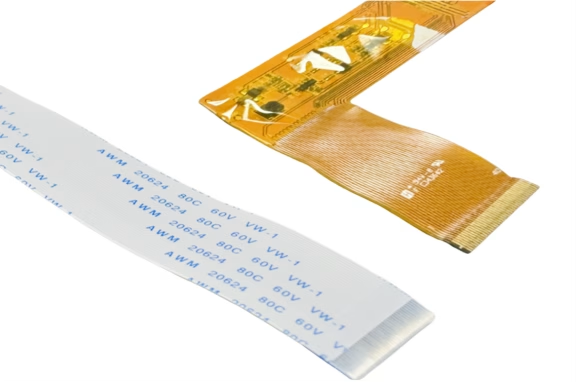
Table of Contents
In the rapidly evolving world of electronics, where devices demand increasingly thinner designs, higher reliability, and dynamic functionality, flexible interconnects have become indispensable. Flexible Flat Cables (FFC) and Flexible Printed Circuits (FPC) stand out as two primary technologies addressing these needs. They offer significant advantages over traditional rigid printed circuit boards (PCBs), such as reduced weight, increased flexibility, and improved space efficiency, making them ideal for space-constrained environments and complex geometries.
While both FFC and FPC serve similar purposes, providing crucial links within electronic devices, they possess distinct architectures, manufacturing processes, and performance characteristics. Understanding these differences is paramount for engineers and designers to select the optimal solution for their specific application, ensuring both functionality and cost-efficiency. This guide will delve deep into FFC and FPC, exploring their construction, capabilities, applications, and the critical factors to consider when making your choice.
1. What is FFC (Flexible Flat Cable)?

Flexible Flat Cables (FFC), often referred to as ribbon cables, represent a simpler form of flexible interconnect. Their construction is straightforward: multiple flat, parallel conductors, typically made of thin copper foil, are sandwiched between two layers of insulating film, commonly polyester (PET) or Kapton (polyimide). This construction gives them their characteristic flat, ribbon-like appearance.
FFCs are known for their standardized pitch (the distance between the centers of adjacent conductors) and width, which allows for mass production and relatively low manufacturing costs. They are generally designed for “wire-to-board” applications, connecting a flexible cable to a rigid PCB circuit, or even “wire-to-wire” configurations. FFCs are excellent for static or limited flexing applications where components need to be connected across a small distance without significant movement. While they offer flexibility, their flat conductors are less robust under continuous, dynamic bending compared to FPCs.
Common applications for FFC include connections in consumer electronics like printers, scanners, DVD players, laptops, and various display applications where a simple, reliable, and low-profile connection is needed without complex routing or high-speed data transmission requirements.
2. What is FPC (Flexible Printed Circuit)?

Flexible Printed Circuits (FPC), on the other hand, are a more advanced and versatile form of flexible interconnect. An FPC is essentially a flexible version of a traditional PCB. It consists of conductive traces, usually etched from a copper foil, laminated onto a flexible polyimide (PI) substrate. Unlike FFCs, FPCs can feature intricate circuit designs, including varying trace widths, complex routing, via holes, and even multiple layers, much like a conventional rigid PCB.
The manufacturing process for FPCs involves photo-etching, plating, and laminating, similar to rigid PCB fabrication, making it more complex and generally higher in cost than FFC. However, this complexity allows for greater design freedom, higher density, and the ability to integrate passive and active components directly onto the flexible substrate. FPCs are highly durable and excel in applications requiring frequent or dynamic flexing, thanks to the inherent properties of polyimide and the etched trace design.
FPCs are critical in high-performance and compact electronic devices such as smartphones, wearables, medical devices, automotive electronics, and aerospace systems. Their ability to provide superior signal integrity, impedance control, and EMI shielding (often through integrated ground layers) makes them suitable for high-speed data transmission and sensitive electronic systems.
3. Key Differences: FFC vs FPC
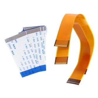
The distinction between FFC and FPC lies in several critical areas, influencing their suitability for different electronic projects.
3.1 Structural & Material Composition
The fundamental difference lies in their construction. FFCs are made from parallel copper traces laminated between two layers of polyester or Kapton film. This structure is akin to a “ribbon” of conductors. FPCs, conversely, are fabricated by etching intricate copper circuit patterns onto a flexible polyimide film, allowing for more complex routing and multi-layer designs. Polyimide offers superior thermal stability and mechanical strength compared to polyester, making FPCs more resilient.
3.2 Flexibility and Durability
While both are flexible, their durability under repeated bending differs significantly. FPCs, especially those made with polyimide and optimized trace designs, are engineered for high flex cycles, making them ideal for dynamic applications like hinge mechanisms in flip phones or robotic arms. FFCs are better suited for static installations or applications with very limited, infrequent bending. Continuous dynamic flexing can lead to fatigue failures in FFCs more readily than in robust FPCs.
3.3 Design Complexity and Density
FFCs are inherently simple in design, consisting of uniform, parallel conductors. This simplicity limits their ability to handle complex signal routing or high component density. FPCs, leveraging PCB manufacturing techniques, can support multi-layer designs, varied trace widths, controlled impedance lines, and integrate surface-mount components directly. This makes FPCs suitable for highly compact and sophisticated electronic devices where space is at a premium and complex circuitry is required.
3.4 Electrical Performance and EMI Shielding
For high-speed digital signals and sensitive analog circuits, FPCs generally offer superior electrical performance. Their ability to incorporate ground planes and controlled impedance traces helps maintain signal integrity and provides effective EMI (Electromagnetic Interference) shielding. FFCs, with their open, parallel conductor structure, typically offer less protection against EMI and are less suitable for high-frequency or high-speed data transmission where crosstalk and impedance matching are critical.
3.5 Cost and Manufacturing Process
Manufacturing FFCs is a simpler, more automated process involving stamping and lamination, leading to lower unit costs, especially for high volumes. FPC manufacturing involves more complex processes like photolithography, etching, and plating, which are similar to rigid PCB fabrication. This complexity, coupled with the cost of polyimide materials, makes FPCs generally more expensive than FFCs. However, the higher cost often justifies the superior performance and design capabilities. The table below summarizes these key differences:
| Feature | Flexible Flat Cable (FFC) | Flexible Printed Circuit (FPC) |
| Structure | Parallel copper conductors laminated between insulating films (polyester, Kapton). | Etched copper traces on a flexible polyimide (PI) substrate; can be multi-layer. |
| Materials | Polyester (PET), Kapton (PI), Copper foil. | Polyimide (PI), Copper foil, Adhesives, Coverlay. |
| Design Complexity | Simple, parallel conductors, fixed pitch. | Complex, intricate routing, varied trace widths, multi-layer, vias, component integration. |
| Flexibility/ Durability | Good for static or limited flexing. Less durable for dynamic bending. | Excellent for dynamic flexing, high reliability under repeated bending. |
| Electrical Performance | Lower signal integrity, limited EMI shielding, less impedance control. | High signal integrity, excellent EMI shielding (with ground layers), precise impedance control. |
| Cost | Lower manufacturing cost, ideal for high volume, simple connections. | Higher manufacturing cost, suitable for complex, high-performance applications. |
| Applications | Printers, scanners, simple display connections, laptops ( internal static connections). | Smartphones, wearables, medical devices, automotive, aerospace, high-speed data. |
| Connector Types | Often ZIF (Zero Insertion Force), LIF (Low Insertion Force). | ZIF/LIF, but also more specialized solderable connectors or direct soldering. |
4. FFC vs FPC Connectors: A Closer Look
The choice between FFC and FPC also significantly impacts connector selection. While both can utilize similar types of connectors, there are crucial differences to understand:
4.1 FFC Connectors
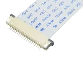
FFC connectors are primarily designed to mate with the flat, ribbon-like cables. They typically feature a high-density, narrow profile, making them ideal for tight spaces. The most common types are Zero Insertion Force (ZIF) and Low Insertion Force (LIF) connectors. ZIF connectors, in particular, are popular because they allow for easy insertion and removal of the FFC without stressing the cable or connector pins, ensuring a reliable connection for wire-to-board applications. They are standardized and readily available, contributing to the cost-efficiency of FFC solutions.
4.2 FPC Connectors
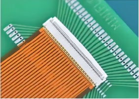
FPC connectors are designed to link flexible printed circuits to a rigid PCB or module. They also often come in ZIF/LIF configurations, especially for simpler FPCs that function similarly to FFCs in basic connectivity. However, FPC connectors can be more diverse. Due to the F PC’s ability to integrate components and complex designs, some FPCs are designed for direct soldering to a rigid board, or they might utilize highly specialized, compact connectors that allow for higher pin counts, better retention, and enhanced signal integrity suitable for demanding environments. The “one end soldered to the PCB” characteristic of FPC connectors highlights their integration into complex systems.
5. When to Choose FFC or FPC?

Making the right choice between FFC and FPC depends on a comprehensive evaluation of your project’s requirements, budget, and performance expectations.
5.1 Choose FFC When:
- Cost-Efficiency is Key:If budget is a primary concern and your application doesn’t require extreme performance.
- Simple Connectivity:For basic interconnections between two points without complex routing or high-speed data.
- Static or Limited Flexing:When the cable will not undergo frequent or severe bending and twisting.
- Standardized Solutions:If off-the-shelf, readily available components and connectors are preferred.
- Space is Tight but Simple:FFCs offer a very thin profile, ideal for basic connections in compact devices.
- High Volume Production:Simpler manufacturing leads to lower unit costs at scale.
5.2 Choose FPC When:
- Dynamic Flexing is Required:For applications involving continuous movement, bending, or torsion (e.g., hinges, robotic parts, wearables).
- High Signal Integrity/EMI Shielding:When dealing with high-frequency signals, sensitive analog circuits, or environments prone to electromagnetic interference.
- Complex Circuitry:If your design requires multiple layers, varied trace widths, integrated components (SMT), or controlled impedance.
- Extreme Miniaturization:For the most compact devices where space is extremely limited and component integration on the flexible substrate is necessary.
- Harsh Environments:Polyimide-based FPCs offer better thermal, chemical, and mechanical resistance.
- Customization and High Performance:When a custom-engineered solution is needed for specialized performance requirements.
6. Industry Trends and Innovations
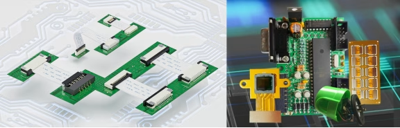
Both FFC and FPC technologies are continually evolving to meet the demands of modern electronics:
- Miniaturization:The drive for smaller, thinner devices pushes for finer pitch FFCs and higher density FPCs, allowing for more connections in less space.
- Enhanced Performance:Advancements in FPC materials and manufacturing techniques are leading to improved signal integrity for high-speed data, better thermal management, and enhanced durability for extreme flex cycles.
- Integration:FPC technology is moving towards greater integration, allowing more components, sensors, and even antennas to be directly fabricated or mounted onto the flexible substrate, reducing overall system size and complexity.
- Automation:The manufacturing process for both FFC and FPC is becoming increasingly automated, leading to higher precision, improved reliability, and potentially lower costs over time.
- Environmental Friendliness:A growing focus on sustainable materials and processes is influencing the development of greener FFC and FPC solutions.
For custom requirements, consulting manufacturers specializing in flexible connectivity can provide tailored solutions that leverage the latest advancements in either FFC or FPC technology.
7. FFC and FPC FAQs
Question 1: Can FFC and FPC be used interchangeably?
Rarely. While both are flexible interconnects, their structural, performance, and cost differences make them suitable for very distinct applications. Attempting to interchange them without careful consideration of these factors often leads to performance issues or unnecessary cost.
Question 2: Which is more durable, FFC or FPC?
Generally, FPC is more durable, especially in applications requiring dynamic, continuous flexing. The polyimide substrate and etched trace design of FPCs are inherently more resilient to repeated bending and environmental stresses compared to the simpler construction of FFCs.
Question 3: Are FFC and FPC connectors compatible ?
While some FFC and FPC connectors may look similar (e.g., ZIF connectors), it’s crucial to verify compatibility. Connector specifications, such as pitch, number of pins, cable thickness, and retention mechanisms, must match precisely. Using an incompatible connector can lead to unreliable connections or damage.
Question 4: What is the main cost driver for FPC?
The main cost drivers for F PC include the raw material (polyimide film is more expensive than polyester), the complex multi-step manufacturing process (etching, plating, lamination), and the higher design complexity, especially for multi-layer FPCs with integrated components.
Question 5: What is the primary material difference between FFC and FPC?
FFCs typically use polyester as the insulating film with flat copper conductors, while FPCs commonly use polyimide (PI) as the flexible substrate for etched copper traces.
Question 6: Can components be mounted directly on an FFC?
No, FFCs are primarily designed for simple point-to-point electrical connections and do not support direct component mounting. FPCs, however, are designed to integrate components.
Question 7: What does ZIF stand for in the context of connectors?
ZIF stands for Zero Insertion Force. These connectors allow FFCs or FPCs to be inserted and removed with minimal force, preventing damage to the cable and contacts.
8. Summary
Flexible Flat Cables (FFC) and Flexible Printed Circuits (FPC) are cornerstones of modern compact electronics, each offering unique advantages. FFCs are characterized by their simple, parallel conductor design, cost-effectiveness, and suitability for static or limited-flexing applications with standardized connections. FPCs, conversely, are miniature, flexible PCBs, offering complex circuitry, multi-layer capabilities, superior signal integrity, robust dynamic flexing, and component integration, making them ideal for high-performance and demanding environments. The choice between these two flexible interconnects hinges on a careful analysis of structural requirements, desired performance, durability needs, and budget constraints. Understanding these distinctions is crucial for optimal design and manufacturing in today’s electronic landscape.
Contact us
WhatsApp: +86-13570802455
Wechat: +86-13570802455
Email: [email protected]