Inductors, Coils, Chokes
All three are essentially inductors, and the differences in their names stem from the different emphasis on design goals, structural features, and application scenarios.
1. What are Inductors, Coils and Chokes?
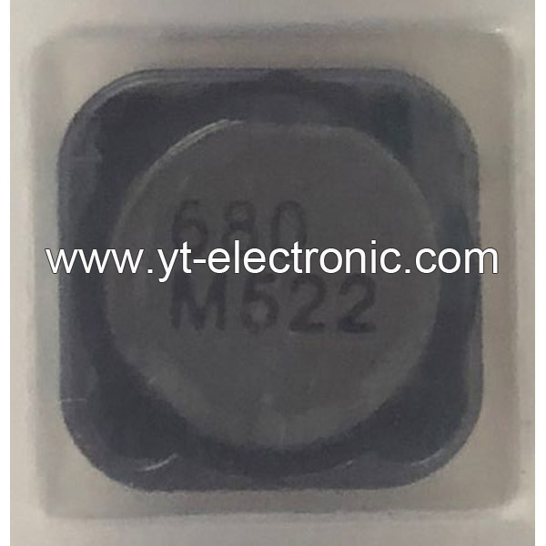
Inductor: A passive component that uses the self-inductance effect as its core principle to store magnetic energy and resist current changes through the principle of electromagnetic induction. Its basic functions include filtering, oscillation, waveform transformation, and cooperating with capacitors to achieve resonant circuits.
Coil: A multi-turn wire structure wound by enameled wire, usually as a physical implementation form of an inductor, widely used in electromagnets, transformers, radio transmitters, and other scenarios.
Choke: A specially designed inductor that is used to suppress high-frequency AC signals (such as radio frequency interference) while allowing DC or low-frequency current to pass. Its core function is to block unnecessary AC components through high reactance.
2. What are the Structural Differences between Coils and Chokes?
Coil: Usually a hollow or cored winding structure, the core material (such as ferrite, alloy powder core) can significantly increase the inductance value. For example, the "tank circuit" in the radio transmitter often uses a high-Q hollow coil.
Choke: The design emphasizes high-frequency impedance characteristics, often using core materials and optimizing the winding method to reduce distributed capacitance. For example, the high-frequency noise of the switching power supply is suppressed by the choke in the power supply filter circuit.
3. What are Inductors, Coils and Chokes Used for?
1)Coil:
Electromagnetic equipment: such as transformer windings, and relay coils.
High-frequency circuits: such as RF matching networks, and antenna tuning.
2)Choke:
Power supply circuit: suppress AC ripple in DC power supply.
Signal processing: block radio frequency interference (RFI) from entering sensitive circuits.
3)Inductor (general purpose):
Energy storage and filtering: such as energy storage elements in LC filter circuits.
Energy conversion: such as step-up/step-down inductors in switching power supplies.
4. Reasons for Naming Differences
Function-oriented naming: For example, "choke" emphasizes its function of suppressing AC ("Choke" means "choke"), while "coil" focuses on the physical structure description.
Application scenario distinction: For example, "winding" is used to describe the coil in a motor or transformer, emphasizing its role in energy transmission; "bead" specifically refers to a small inductor used for high-frequency filtering.
5. Typical Brands for Inductors, Coils and Chokes
BOURNS
TDK
VISHAY
ABRACON
Murata
TOKO
6. Inductors, Coils and Chokes FAQs
1) What are the differences between inductors, coils, and chokes?
Inductors are mainly used for energy storage and filtering;
Coils refer to general components with winding structures;
Chokes are inductors specifically used to suppress high-frequency noise, commonly found in power supplies and RF circuits.
2) How do chokes achieve high-frequency signal isolation?
Chokes use the high-frequency impedance characteristics of inductors (XL=ωL) to allow DC and low-frequency signals to pass while blocking high-frequency interference. For example, RF chokes can limit high-frequency noise to local circuits.
3) What parameters should be considered when selecting chokes?
Key parameters include inductance value, tolerance (such as ±20%), saturation current (such as 3.75A), DC resistance (such as 37mΩ), and self-resonant frequency (such as 65MHz). Common-mode chokes also need to consider common-mode impedance (such as 300Ω).
4) How should inductors be selected in high-frequency circuit design?
Shielded inductors (such as Power Shielded Inductors) should be preferred to reduce electromagnetic interference; high-frequency transformers should adopt planar or ferrite core designs to optimize performance.
5) In what scenarios do common-mode chokes need to be used?
Common-mode chokes (such as 744212510 models) are often used to suppress common-mode noise in power lines or communication lines and are suitable for EMI filtering and high-speed data transmission systems.
6) What is the role of chokes in radio frequency (RF) circuits?
In broadband communications (such as fiber optic networks), RF chokes can isolate high-frequency interference in signal paths to ensure signal integrity.
7) What are the design points of high-frequency transformers?
The core material (such as ferrite), winding structure, and shielding process need to be optimized to meet high-frequency efficiency and low-loss requirements. Planar transformers are widely used due to their small size and good heat dissipation.
8) How does the packaging form of high-power inductors affect performance?
For example, SMD packaged inductors such as the IHLP1616BZET1R0M01 use molded composite cores and combine high current carrying capacity (such as 10.5A saturation current) with compact size (4.06×4.06×1.8mm).


