ICT Testing Principles
In-Circuit Test (ICT) is a method of detection commonly used in electronics manufacturing to test whether electronic components on a Printed Circuit Board (PCB) work normally.
Circuit boards are used to test the functionality and connectivity by applying voltages and signals.
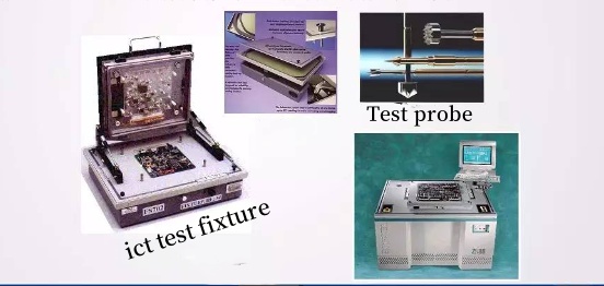
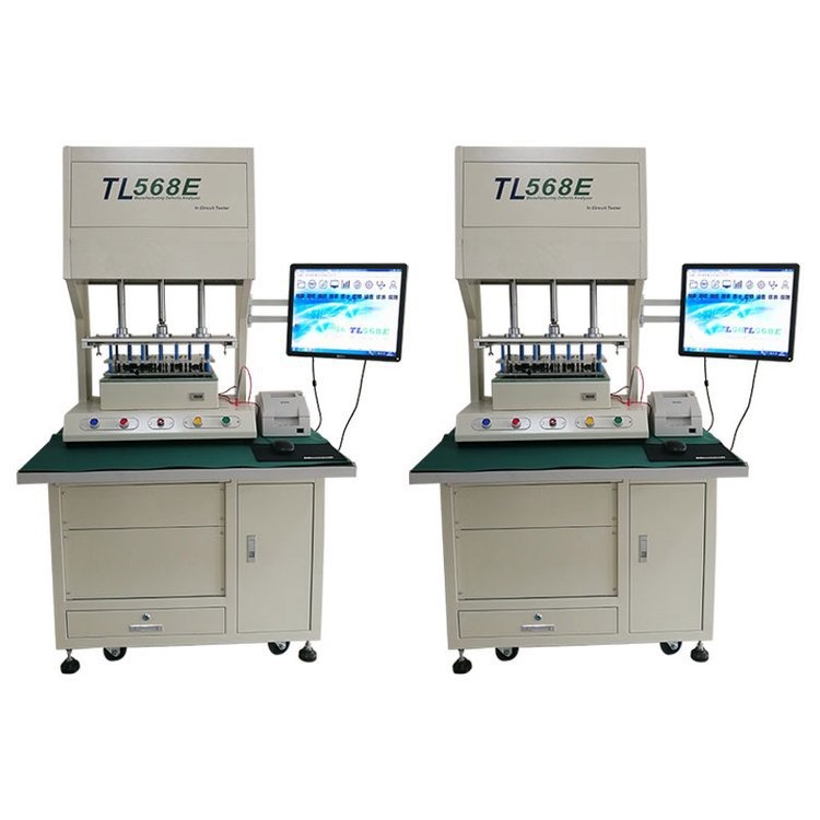
ICT testing relies on the use of a ICT fixture and an ICT probe in order to make contact with the components located on the circuit board. Then, apply voltage, signal and test mode in order to evaluate the component's performance.
These are the fundamental principles of ICT Testing:
1. Test pins and test fixture: The test pins are a special fixture designed to ensure physical contact between electronic components and the pins.
Metal pins can be connected to a tester fixture and then to the pins on a board. The pins and test fixture are designed based on the layout of the circuit board and the locations of components.
2. Circuit connection: Test pins are connected to pins on the PCB. The test system may apply voltages, test patterns, or signals to specific pins.
3. Test mode and signal application: The test system applies voltage to pins on the circuit board in accordance with the predetermined test procedures.
The signals can be either digital or analog depending on the character of the component that is being tested. The system compares the results with the test result.
4. Performance evaluation: The test system can assess the component's performance based on the data it records. The test system will indicate if the actual performance does not match the expectation.
ICT Testing: What Is Its Role?

ICT testing improves the quality of products, increases production efficiency, lowers costs, increases product reliability and safety and meets all traceability requirements.
ICT (In Circuit Test) is a key component in the manufacture and maintenance of electronic products. Its main functions include:
1. Quality Control: Testing ICT products for quality is a way to ensure the product's quality.
The circuit board can be checked to see if the electronic components are functioning properly and if the connections are correct.
PCB Manufacturers can improve product quality by identifying and detecting defects.
2. Control of the manufacturing process: ICT tests can be used to monitor different stages in electronic product manufacture.
It helps manufacturers find and fix problems in the production process early, preventing defective products from reaching the market. It can save you time and money.
3. Assembly Verification: ICT Testing can be used to verify the functionalities of assembled electronic circuit boards at the end of assembly.
It can help detect assembly problems such as bent pins or incorrectly installed components to ensure that the final product performs according to expectations.
4. Fault detection: ICT can diagnose and repair faults.
ICT can be used to detect faulty electronic components and reduce repair costs. It can also help speed up repair times, improve product maintenance, and shorten repair times.
5. Traceability: The ability to track test results, electronic component batch information and suppliers.
It helps establish product traceability. It can be traced to a specific batch of components to determine the cause of a problem.
6. Cost saving: ICT testing reduces costs by automating the test process and improving testing speed and accuracy. It reduces production and repair costs.
7. Improve product reliability: ICT testing improves product reliability by detecting potential electronic component issues and fixing them.
This is especially important for applications that need high durability and stability, like aerospace, medical equipment etc.
What Is the Main Purpose of ICT Testing?
ICT (In Circuit Test) is used primarily to measure the performance of electronic circuits, components, and connections to ensure correct operation.
These are the main measurements for ICT testing.
1.Component function: ICT Testing checks if electronic components (such a resistors capacitors diodes transistors etc.) are operating normally. Component Function: ICT testing checks whether electronic components (such as resistors, capacitors, diodes and transistors) are operating normally.
Test systems that apply voltages and signals can verify whether these components are operating within parameters such as resistance, capacitance, and switch states.
2. Component Connectivity: The ICT tests are used to ensure that electronic components have the correct connections. The system tests the pin connectivity of components to make sure that it matches the circuit board layout.
3. Circuit connectivity: ICT tests circuit connectivity to ensure that the connections on the board are correct. It tests the circuit paths, wires and jumpers on the circuit board. It checks that they are not short-circuited or open.
4. Power and Griund Conntections: ICT Testing checks the power and ground connections of electronic components. It ensures that the components are powered properly and not damaged by incorrect voltages or currents.
5. Single transmission: ICT testing is also able to verify digital and analog signal transmission on circuit boards. It ensures that the signal's transmission path is not distorted or interfered with.
6. Circuit board layout: ICT testing is able to check if the circuit board layout matches the design specifications. This includes checking the component placement, pin arrangement and connection points.
7. Fault Detection: ICT testing can also detect faults such as open circuits, short circuits or component failures. It allows for early detection of problems and the implementation of measures.
Testing ICT Usually Involves the Following Steps
1. Create a test stand: Using the layout of the circuit board and the location of the components, create a stand to test the connection between the test pins and the pins on the board.
2. Create test procedures: Write test procedures that define the pins to be tested, and how they should be tested. This includes determining expected responses, applying voltages and signals, and creating test patterns.
3. Build the test fixture: This includes installing the pins for the tests and connecting the cables.
4. Test the board: Place it in the test fixture, and follow the test procedure. The test system will record pin responses and apply voltages.
5. Analyze results: Determine if the electronic components work properly based on the test results. The faulty component can be marked for further processing.
6. Reports and records: Generate test reports for recording test results and issues. These records are used for quality control, traceability and other purposes.


