What Are the Effects of High Temperature on PCB Boards?
Although PCB materials are designed to withstand a certain level of thermal energy, circuit performance is affected when the temperature exceeds threshold.
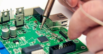
Thermal energy can be a threat to printed
circuit boards (PCBs).
The PCB materials have been designed to resist certain levels of heat, but circuit performance is
affected by temperature, especially when operating at high frequencies. Circuit designers who have a
thorough understanding of various parameters can accurately describe how circuit materials react when
temperatures rise. They can then select heat-resistant PCB material and design circuits to withstand
specific levels of thermal energy.
Thermal Energy comes from many forms,and the impact it has on circuits can vary from
one case to another, especially with the increasing density of board assemblies and the trend towards
smaller and lighter designs. Thermal energy is generated either by the components on the board, or
external heat sources. Designers of high-power radars are well aware of the heat generated by vacuum
tubes amplification devices like klystrons or traveling wave tubes. Recent use of high density
amplification semiconductors like gallium nitride transistors (GaNs) has increased the power of
RF/microwave signal, but also brought hot spots into the spotlight. Heat sources outside the PCB can
also cause circuit temperature to increase and reliability problems. Understanding the behavior of
RF/microwave materials at high temperatures is the key to designing circuits with the least impact from
heat sources.
Thermal energy expands most materials. Circuit materials are not an exception.
Microwave circuits have smaller features at high frequencies because the wavelengths become shorter.
These feature sizes may be distorted as the board expands because of increased temperature. As the
demand for smaller designs increases, circuits are being designed with materials that have higher
dielectric constants. This results in smaller circuit features, at a certain frequency and wavelength.
Circuit materials expand at high temperatures, changing their shape and causing conductor impedance to
shift away from desired values (usually 50O). Circuits may experience linear loss, distortion and even
frequency shifts at high temperatures due to changes in transmission lines dimensions.
Circuit board composites are composed of dielectric metal and dielectric layers. These
materials expand at different rates when exposed to heat. The coefficient of thermal contraction (CTE)
parameter describes this behavior. It is measured in parts per million. Ideal CTE values for PCB
dielectric layers should be similar to those of copper or other conductive materials laminated onto the
dielectric material. This will ensure that both materials expand at the same rate at high temperatures,
and prevent stress at the interface of the materials. Circuit designers are often concerned about the
reliability of circuit components when exposed to high temperatures. This includes plated through-holes
(PTHs), which connect different layers on a multilayer board, as well as the junction between dielectric
and conductive materials.
When high-dielectric-constant circuit materials are used to minimize circuit function and
size, such as Rogers Corp.’s low-loss RO3010(tm) circuit laminate, which has a
dielectric constant (Dk) of 10.2 (thickness) measured in the z-axis at 10 GHz and a tolerance of +-0.30
across the board, high temperatures will affect the size and spacing of transmission lines, especially
as circuit size is reduced due to the high Dk of the laminate. Circuits designed for millimeter wave
frequencies also have very fine lines and spacing. The expansion of the board due to high temperatures
can affect the performance of such circuits.
The line width and transmission lines spacing together determine the degree to which various
components in the circuit are coupled. At this same time, the circuit size plays a crucial
role in determining center frequency of resonant circuit. In a bandpass filter with edge coupling, for
example, the difference in coefficient of thermal contraction (CTE), between the dielectric and
conductor, can cause physical changes between the coupled resonators. This may affect the filter’s
performance. The passband frequency and bandwidth is adversely affected.
Shenzhen yt-electronic: A lower coefficient of thermal contraction (CTE) in printed
circuit board materials means that material expands less as the temperature increases. In general, a CTE
value that is lower is considered ideal. According to common engineering practices the CTE of PCB
materials must be kept below 70 ppm/degC in order to maintain the reliability of the board. These
materials are ideal for circuits that operate in the millimeter-wave band or require higher precision
dimming.


